An ADC has an analogue reference voltage $V_{REF}$ or current against which the analogue input is compared. The digital output tells us what fraction of the reference voltage or current is the input voltage or current. So if we have N-bit ADC, there are $2^N$ possible output codes, and the difference between each output code is $\frac{V_{REF}}{2^N}$.
Resolution of ADC
Every time you increase the input voltage by $V_{REF}/2^N$ Volt, the output code will increase by one bit. This means that the least significant bit (LSB) represents $V_{REF}/2^N$ Volt, which is the smallest increment that the ADC actually can \textit{resolve}. Then one can say that the \textit{resolution} of this converter is $V_{REF}/2^N$ because ADC resolve voltages as small as such value. Resolution may also be stated in bits.
Because the resolution is $V_{REF}/2^N$, better accuracy / lower error can be achieved as: 1) use a higher resolution ADC and/or 2) use a smaller reference voltage. The problem with high-resolution ADC is the cost. Moreover, the higher resolution / lower $V_{REF}/2^N$, the more difficult to detect a small signal as it becomes lost in the noise thus reducing SNR performance of the ADC. The problem with reducing $V_{REF}$ is a loss of input dynamic range.
Hence the ADC's resolution indicates the number of discrete values that can be produced over the range of analogueue values and can be expressed as:
$$ K_{ADC} = (V_ \mathrm {REF} - V_ \mathrm {min})/N_{max}$$
where $V_ \mathrm {REF}$ is maximum (reference) voltage that can be quantified, $V_ \mathrm {min}$ is minimum quantifiable voltage, and $N_{max} = 2^M$ is the number of voltage intervals ($M$ is ADC's resolution in bits). The ADC's output code can be represented as:
$$ADC_ \mathrm {Code} = \textrm{round}\left[ (V_ \mathrm {input}-V_ \mathrm {min})/K_{ADC} \right]$$
The lower reference voltage $V_{REF}$, the smaller range of voltages with greater accuracy one can measure. This is a common way to get better precision from an ADC without buying a more expensive ADC with higher resolution.
Quantisation error
As the input voltage in ADC increases towards $V_{REF}/2^N$, the output still remains at zero because a range of input voltages is represented by a single output code. When the input reaches $V_{REF}/2^N$, the output code changes from 000 to 001.
The maximum error in ADC is 1 LSB. This 0 to 1 LSB range is known as the ``quantisation
uncertainty'': there is a range of analogue input values that could have caused any given code.
Linearity and Linearity errors
The accuracy of analogue to digital conversion has an impact on overall system quality and efficiency. To be able to improve accuracy you need to understand the errors associated with the
ADC and the parameters affecting them.
Differential Linearity Error
Differential Linearity Error (DLE) describes the error in step size of an ADC: it is the maximum deviation between actual steps and the ideal steps (code width). Here ``ideal steps''' are not for the ideal transfer curve but for the resolution of the ADC. The input code width is the range of input values that produces the same digital output code.
Ideally analogue input voltage change of 1 LSB should cause a change in the digital code. If an analogue input voltage greater than 1 LSB is required for a change in digital code, then the ADC has the differential linearity error.
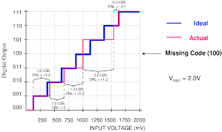
Here each input step should be precisely 1/8 of reference voltage. The first code transition from 000 to 001 is caused by an input change of 1 LSB as it should be. The second transition, from 001 to 010, has an input change that is 1.2 LSB, so is too large by 0.2 LSB. The input change for the third transition is exactly the right size. The digital output remains
constant when the input voltage changes from 4 LSB to 5 LSB, therefore the code 101
can never appear at the output.
When no value of input voltage will produce a given output code, that code is missing from the ADC transfer function. In data sheets of many ADC it is specified ``no missing codes''; this can be critical in some applications like servo systems.
Integral Linearity Error
Integral Linearity Error (ILE) describes the maximum deviation of ADC transfer function from a linear transfer curve (i.e. between two points along the input-output transfer curve). It is a measure of the straightness of the transfer function and can be greater than the differential non-linearity. In specifications, an ADC is described sometimes as being ``x bits linear.''
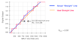
The ADC input is usually connected to an operational amplifier, maybe a summing or a differential amplifier which are linear circuits and process an analogue signal. As the ADC is included in the signal chain, we would like the same linearity to be maintained at the ADC level as well. However, inherent technological limitations make the ADC non-linear to some extent and this is where the ILE comes into play.
For each voltage in the ADC input there is a corresponding word at the ADC output. If an ADC is ideal, the steps are perfectly superimposed on a line. But most of real ADC exhibit deviation from the straight line, which can be expressed in percentage of the reference voltage or in LSBs.
The ILE is important because it cannot be calibrated out. Moreover, the ADC non-linearity is often unpredictable: it is difficult to say where on the ADC scale the maximum deviation from the ideal line is. Let's say the electronic device we design has an ADC that needs to measure the input signal with a precision of $\alpha$\% of reference voltage. Due to the ADC quantisation, if we choose a N-bit ADC, the initial measurement error is $E_{ADC} = \pm 0.5$ LSB, which is called the quantisation error:
$$ADC_{qantiz.error} = E_{ADC}/2^N $$
For instance, with 12-bit ADC and measurement error $\pm 1/2$ LSB, quantisation error will be $ADC_{qantiz.error} = \frac{1}{2 \cdot 2^{12}} \approx 0.0012 \% $. If we need to measure the input signal with precision of 0.1\% of VREF, 12-bit ADC does a good job. However, if the INL is large, the actual ADC error may come close to the design requirements of 0.5\%.
Signal-to-Noise ratio for ADC
Signal-to-Noise Ratio (SNR) is the ratio of the output signal amplitude to the output noise level. SNR of ADC usually degrades as frequency increases because the accuracy of the comparator(s) within the ADC degrades at higher input slew rates. This loss of accuracy shows up as noise at the ADC output.
Noise in an ADC comes from four sources:
- quantisation noise;
- noise generated by the ADC itself;
- application circuit noise;
- jitter;
The non-linearity of the ADC can be described as input to output transfer function of:
$Output = Input^{\alpha}$
Quantisation noise
Quantisation noise results from the quantisation process - the process of assigning an output code to a range of input values. The amplitude of the quantisation noise decreases as resolution increases because the size of an LSB is smaller at higher resolutions, which reduces the maximum quantisation error. The theoretical maximum of SNR for an ADC with a full-scale sine-wave input derives from quantisation noise
and is about $6.02\cdot N + 1.76$ dB.
Noise generated by the ADC itself
The problem can be in high capacitance of ADC output or input. Device input capacitances causes noise on the supply line. Discharging these capacitances adds noise to the ADC substrate and
supply bus, which can appear at the input as noise.
Minimising the load capacitance at the output will minimise the currents needed to charge and
discharge them, lowering the noise produced by the converter itself. This implies that one
output pin should drive only one input device pin (use a fan-out of one) and the length of the
ADC output lines should be as short as possible.
Application circuit noise
Application circuit noise is that noise seen by the converter as a result of the way the circuit is designed and laid out, for instance, noisy components or circuitry: noisy amplifiers, noise in resisters.
Amplifier noise is an obvious source of noise, but it is extremely difficult to find an amplifier with noise and distortion performance that will not degrade the system noise performance with a high resolution (12-bit or higher) ADC.
We often think of resistors as noisy devices, but choosing resistor values that are as low as
practical can keep noise to a level where system performance is not compromised.
Jitter
A clock signal that has cycle-to-cycle variation in its duty cycle is said to exhibit jitter. Clock jitter causes an uncertainty in the precise sampling time, resulting in a reduction of dynamic performance.
Jitter can result from the use of a poor clock source, poor layout and grounding. One can see that the steps of digital signal in case of jitter are rough and non-uniform.
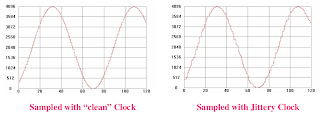
SNR performance decreases at higher frequencies because the effects of jitter get worse.
Types of ADC
There are different type of ADC schemes, each of them has own advantages and disadvantages.
For example, a Flash ADC has drifts and uncertainties associated with the comparator levels, which lead to poor uniformity in channel width and therefore poor linearity.
Poor linearity is also apparent for SAR ADCs, however it is less than that of flash ADCs. Non-linearity in SAR ADC arises from accumulating errors from the subtraction processes.
Wilkinson ADCs can be characterised as most linear ones; particularly, Wilkinson ADCs have the best (smallest) differential non-linearity.
Flash (parallel encoder) ADC
Flash ADCs are made by cascading high-speed comparators. For an N-bit ADC, the circuit employs 2N-1 comparators. A resistive-divider with 2N resistors provides the reference voltage. The reference voltage for each comparator is one least significant bit (LSB) greater than the reference voltage for the comparator. Each comparator produces a 1 when its analogue input voltage is higher than the reference voltage applied to it. Otherwise, the comparator output is 0.
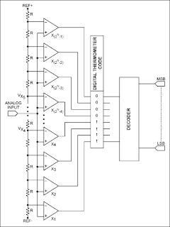 [the Image from the reference, (c) Maxim-ic]
The key advantage of this architecture is very fast conversion times, which is suitable for high-speed low-resolution applications.
The main disadvantage is its high power consumption. The Flash ADC architecture becomes prohibitively expensive for higher resolutions. [the reference used, (c) Maxim-ic]
Successive approximation register ADC
Successive-approximation-register (SAR) ADCs are the majority of the ADC market for medium- and high-resolution. SAR ADCs provide up to 5Msps sampling rates with resolutions from 8 to 18 bits. The SAR architecture allows for high-performance, low-power ADCs to be packaged in small form factors. The basic architecture is shown in Fig.~\ref{fig:SARADC}.
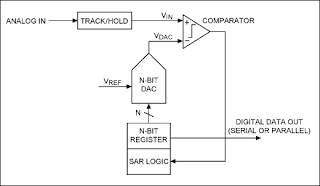 [ the Image from this reference, (c) Maxim-ic]
The analogue input voltage (VIN) is held on a track/hold. To implement the binary search algorithm, the N-bit register is first set to midscale. This forces the DAC output (VDAC) to be VREF/2, where VREF is the reference voltage provided to the ADC.
A comparison is then performed to determine if VIN is less than, or greater than, VDAC. If VIN is greater than VDAC, the comparator output is a logic high, or 1, and the MSB of the N-bit register remains at 1. Conversely, if VIN is less than VDAC, the comparator output is a logic low and the MSB of the register is cleared to logic 0.
The SAR control logic then moves to the next bit down, forces that bit high, and does another comparison. The sequence continues all the way down to the LSB. Once this is done, the conversion is complete and the N-bit digital word is available in the register.
Generally speaking, an N-bit SAR ADC will require N comparison periods and will not be ready for the next conversion until the current one is complete. This explains why these ADCs are power- and space-efficient. Another advantage is that power dissipation scales with the sample rate.[the reference used, (c) Maxim-ic]
No comments:
Post a Comment