Monday, August 18, 2008

How To Write A Scientific Article

A technical paper consists of four sections: Introduction, Formulation of the problem, Results, Conclusion, and Acknowledgements. The purpose of each section is as follows.


Section I: Introduction
The introduction should do the following:
1. Open up the subject.
"Information encryption techniques have been an important and active research area from ancient time to nowadays, which involves a number of applications such as...
"

2. Survey past work relevant to this paper.
"Recently, various methods based on information optics for high dimensional data encryption and decryption have been explored to expand the degrees of freedom for key design and, therefore, to increase the security level of the entire information encryption system [1–6]...."

3. Describe the problem addressed in this paper
,
and show how this work relates to, or arguments, previous work.
"In this paper, we present an alternative data encryption technique based on virtual-optics imaging system..."

4. Describe the assumptions made in general terms
,
and state what results have been obtained. This gives the reader an initial overview of what problem is addressed in the paper and what has been achieved.
"We analyse the sensitivities for some of parameters of such a virtual optics imaging system, with which one is able to design..."

5. Overview the contents of the paper.

``Section II contains our formulation of the problem. Section III contains the experimental data...''


Section II: Formulation of the Problem
This section should do three things:
1. Define the problem to be considered in detail.
Typically this section might begin with something like:
"Consider a virtual–optical imaging system (VOIS) with a single lens. It is schematically shown in Fig. 1..."
The discussion should proceed in this way until the problem is completely defined.

2. Define all terminology and notation used.

Usually the terminology and notation are defined along with the problem itself.
"We refer to as the discrete Fresnel diffraction (DFD) transformation and express it as following
equation.."


3. Develop the equations

on which your results will be based and/or describe any experimental systems.
"In addition, the transmission function of imaging lens should also be described with its discrete
mode in order to carry out numerical simulation: <math here> "


Section III: Results
This section presents the detailed results you have obtained.
If the paper is theoretical, you will probably show curves obtained from your equations.
If the paper is experimental, you will be presenting curves showing the measurement results.
In order to choose the proper curves to present, you must first be clear what point you are trying to convey to the reader. The curves can then be chosen to illustrate this point. Whether your paper is theoretical or experimental, you must provide a careful interpretation of what your results mean and why they behave as they do.


Section IV: Conclusion
This section should summarize what has been accomplished in the paper.
Many readers will read only the Introduction and Conclusion of your paper. The Conclusion should be written so they can be understood by someone who has not read the main work of the paper. This is the common format for an engineering paper. Of course, the names of the sections may differ slightly from those above, but the purpose of each section will usually be as described. Some papers include additional sections or differ from the above outline in one way or another. However, the outline just presented is a good starting point for writing a technical paper.


Section V: Acknowledgements
It is good idea to mention here grant programs and people who contributed in the paper. Usually no more than 3-4 sentences.


References:
This post is based on "Fourteen Steps to a Clearly Written Technical Paper" by R. T. Compton, Jr. Examples of text are used from the article: Xiang Peng, Zhiyong Cui, and Tieniu Tan, Information encryption with virtual-optics imaging system, Optics Communications, 2002, 212:235--245.

Thursday, August 14, 2008

Optical encryption attacks to Double Random Phase Encryption

Double Random Phase Encryption (DRPE) technique has been criticised recently for poor security and low cryptography resistance because of its linearity. Recently has the security of DRP started to be thoroughly analysed and a few weaknesses were reported [1,2,3].

Double Random Phase Encryption technique

As it shortly described in [4], the image to be encrypted P is immediately followed by a first random phase mask, which is the first key X. Both the image and the mask are located in the object focal plane of a first lens (see Fig. 1).


In the image focal plane of this lens is therefore obtained the Fourier transform (FT) of the product $ P\cdot X$ . This product is then multiplied by another random phase mask that is the second key Y. Lastly, another FT is performed by a second lens to return to the spatial domain. Since the last FT does not add anything to the security of the system, we will perform all our analyses in the Fourier plane. The ciphered image C is then:

$\displaystyle C = Y \cdot \mathcal{F}(P\cdot X)$ (1)

where F stands for the Fourier transform operation. In most of the paper, we will assume that P is a grey-level image.


Attacks to the DRPE


Several attacks are proposed against the double random phase encryption scheme. Of source, as it mentioned in Javidi's article [4], brute force attack is useless due to huge amount of keys to be tested.

Reducing the number of combinations


More wise attack is the use of approximate version of the phase mask, especially to binary phase mask. Binarization of the phase mask reduces possible combinations dramatically. Of course, the fewer phase levels, the more noise is introduced in the reconstructed image.

In order to reduce the combinations of decryption keys further it is advisable [1,5] to decode with partial window of second key Y.

Plain-text attacks


The main idea of the plain-attack is to compromise an encryption system by specific known images. In Javidi's paper [4] is mentioned Dirac's delta function, uniform (spatially constant) image.

These attacks are demonstrated on computer-generated ciphered images, and the article [4] gives a comprehensive survey of attacks to DRPE. The scheme is shown to be resistant against brute force attacks but susceptible to chosen and known plaintext attacks. A technique to recover the exact keys with only two known plain images is described. Comparison of such technique to other attacks proposed in the literature is provided.

To sum up, with at most three chosen plain-ciphered image pairs, it is possible to recover the two encryption keys and break the system. But it is only theoretical review, no experimental works were provided. Also, there is no quantitative analysis of decryptability: only ``fuzzy'' visual estimations are presented (like ``the image is still recognizable'' [4] on page 6).

Personal remarks


In other terms, the plain image is entirely black except for a single pixel. It can be argued that such a plain image can look suspicious to the authorized user that is to encrypt it.

Why such image is suspicious? There is an example: you are going to encrypt an image printed on a paper. You are attaching the printed piece of paper on a pin upon the input scene and illuminating the input scene. A bright reflection from the input scene gives you an exact encryption key.

Related works: a little survey


As an example of cryptographical analysis and optical encryption cryptoresistance testing, Nauton's article is interesting [6], and iterative attempt to decrypt DRPE images is proposed in [7]. Another successful attempt to crack DRPE encryption method is reported in [7]. More detailed analysis of phase encoding's attack and quantization influence is covered in [8].

Moreover, Nauton published plain-text cryptographic attack method in [2]. The Fourier plane encryption algorithm is subjected to a known-plaintext attack, - he writes in article. So that Fourier plane encryption algorithm is found to be susceptible to a known-plaintext heuristic attack. Nauton applied a SA algorithm [9] to find a phase mask which would approximately decrypt the ciphertext. He successfully decrypted DRPE-coded $ 64\times 64$ image.


Bibliography


1
A. Carnicer, M. Montes-Usategui, S. Arcos, and I. Juvells.
Vulnerability to chosen-cyphertext attacks of optical encryption schemes based on double random phase keys.
Optics Letters, 30:1644-1646, 2005.
2
Thomas J. Naughton Unnikrishnan Gopinathan, David S. Monaghan and John T. Sheridan.
A known-plaintext heuristic attack on the fourier plane encryption algorithm.
Optics Express, Vol. 14, No. 8:3181-3186, 2006.
3
X. Peng, P. Zhang, H. Wei, and B. Yu.
Known-plaintext attack on optical encryption based on double random phase keys.
Optics Letters, 31:1044-1046, 2006.
4
Yann Frauel, Albertina Castro, Thomas J. Naughton, and Bahram Javidi.
Resistance of the double random phase encryption against various attacks.
Optics Express, Vol. 15, No. 16:10253-10265, 6 August 2007.
5
X. Peng, H. Wei, and P. Zhang.
Chosen-plaintext attack on lensless double-random phase encoding in the fresnel domain.
Optics Letters, 31:3261-3263, 2006.
6
David S. Monaghan, Unnikrishnan Gopinathan, Thomas J. Naughton, and John T. Sheridan.
Key-space analysis of double random phase encryption technique.
Applied Optics, Vol. 46, No. 26:6641-6647, 10 September 2007.
7
Guohai Situ, Unnikrishnan Gopinathan, David S. Monaghan, and John T. Sheridan.
Cryptanalysis of optical security systems with significant output images.
Applied Optics, Vol. 46, No. 22:5257-5262, 1 August 2007.
8
David S. Monaghan, Guohai Situ, Unnikrishnan Gopinathan, Thomas J. Naughton, and John T. Sheridan.
Role of phase key in the double random phase encoding technique: an error analysis.
Applied Optics, Vol. 47, No. 21:3808-3816, 20 July 2008.
9
S. Kirkpatrick, C.D. Gellatt, and M.P. Vecchi.
Optimization by simulated annealing.
Science, 220:771-680, 1983.

Sunday, August 3, 2008

Long-time remote shooting with Canon EOS 400D

The Problem: shooting with exposure times more that 30 seconds requires bulb, but we want to automate shooting process.
The Solution: using some common chips and bash script in Linux, we can make a PC-driven remote control device for Canon's digital camera.


What we have

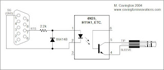
We have the Canon EOS 400D digital camera, a Debian-powered notebook, and necessity of shooting pictures with exposure time longer than 30 seconds. There is good scheme proposed by Michael A. Covington here. Anyway, I'm mirroring it here:


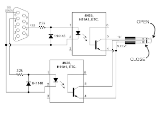
This is a pretty good scheme, but it doesn't work for my Canon EOS 400D: shutter lifting up but not going down.
After personal communications with Michael, I suspect the reason of this problem is in version of the firmware in my camera. Anyway, we have found the solution of the problem.
We have played around a bit and found the solution.

Scheme for Canon EOS 400D

After some cut-and-try iterations, we (I am and my colleague Alexey Ropyanoi) have found out why proposed scheme did not work. Now we proposing the following scheme:

We used one more cascade to control third tip, and it works! Our laboratory Canon EOS 400D now opening and closing shutter by command from computer.

Necessary electric components
To create such remote shooting wire, you need a 4-wire cable (from audio devices or telephone cable), 2.5mm jack (or 3/32 inch jack), electrics chips mentioned above, 9-pin COM-port, and USB-COM adapter (for using this remote shooting wire on novel computers).

The best USB-COM adapter is Profilic 2303 chip: it is the most common chip and it works in Linux "out of the box".


Software
A little program on C, setSerialSignal, is required for remote control of the camera. Source code is here and it can be compiled with GCC:
gcc -o setSerialSignal setSerialSignal.c
Works on Debian GNU/Linux v4.0 r.0 "Etch", gcc version 4.1.2 20061115 (prerelease) (Debian 4.1.1-21).

This is the code:

/*
* setSerialSignal v0.1 9/13/01
* www.embeddedlinuxinterfacing.com
*
*
* The original location of this source is
* http://www.embeddedlinuxinterfacing.com/chapters/06/setSerialSignal.c
*
* This program is free software; you can redistribute it and/or modify
* it under the terms of the GNU Library General Public License as
* published by the Free Software Foundation; either version 2 of the
* License, or (at your option) any later version.
*
* This program is distributed in the hope that it will be useful, but
* WITHOUT ANY WARRANTY; without even the implied warranty of
* MERCHANTABILITY or FITNESS FOR A PARTICULAR PURPOSE. See the GNU
* Library General Public License for more details.
*
* You should have received a copy of the GNU Library General Public
* License along with this program; if not, write to the
* Free Software Foundation, Inc.,
* 59 Temple Place, Suite 330, Boston, MA 02111-1307 USA
*/
/* setSerialSignal
* setSerialSignal sets the DTR and RTS serial port control signals.
* This program queries the serial port status then sets or clears
* the DTR or RTS bits based on user supplied command line setting.
*
* setSerialSignal clears the HUPCL bit. With the HUPCL bit set,
* when you close the serial port, the Linux serial port driver
* will drop DTR (assertion level 1, negative RS-232 voltage). By
* clearing the HUPCL bit, the serial port driver leaves the
* assertion level of DTR alone when the port is closed.
*/

/*
gcc -o setSerialSignal setSerialSignal.c
*/


#include
#include
#include

/* we need a termios structure to clear the HUPCL bit */
struct termios tio;

int main(int argc, char *argv[])
{
int fd;
int status;

if (argc != 4)
{
printf("Usage: setSerialSignal port DTR RTS\n");
printf("Usage: setSerialSignal /dev/ttyS0|/dev/ttyS1 0|1 0|1\n");
exit( 1 );
}

if ((fd = open(argv[1],O_RDWR)) < 0)
{
printf("Couldn't open %s\n",argv[1]);
exit(1);
}
tcgetattr(fd, &tio); /* get the termio information */
tio.c_cflag &= ~HUPCL; /* clear the HUPCL bit */
tcsetattr(fd, TCSANOW, &tio); /* set the termio information */

ioctl(fd, TIOCMGET, &status); /* get the serial port status */

if ( argv[2][0] == '1' ) /* set the DTR line */
status &= ~TIOCM_DTR;
else
status |= TIOCM_DTR;

if ( argv[3][0] == '1' ) /* set the RTS line */
status &= ~TIOCM_RTS;
else
status |= TIOCM_RTS;

ioctl(fd, TIOCMSET, &status); /* set the serial port status */

close(fd); /* close the device file */
}


Sending signals
Compile the program setSerialSignal and make it executable. Below listed signals are described to open and close the shutter:

DTR
setSerialSignal /dev/ttyS0 1 0


Clear DTR
setSerialSignal /dev/ttyS0 0 0


RTS
setSerialSignal /dev/ttyS0 0 1


Clear RTS
setSerialSignal /dev/ttyS0 1 1


Shutter opens at DTR and closes at RTS.


Shell script for remote shooting
To automate the process of taking pictures, it is suitable to use the bash script written by Eugeni Romas aka BrainBug. Here is the modified code:


#!/bin/bash

for i in `seq $3`; do
{
setSerialSignal /dev/ttyUSB0 0 0 &&
sleep $1 && setSerialSignal /dev/ttyUSB0 0 1 &&
sleep 0.3 && setSerialSignal /dev/ttyUSB0 0 0 &&
sleep $2 && setSerialSignal /dev/ttyUSB0 1 1 && echo "One more image captured!" &&
sleep $4;

}
done

echo "Done!"


Script parameters:

1: shutter opening delay
2: exposure time, in seconds
3: amount of shots
4: delay between shots

Example:
make_captures 4 60 30 2
Script can work with USB-COM adaptor and you need to edit it if you have different port.


How does it work
Remote shooting wire is ready, inserting USB-COM adapter with wire and next:
  • Turn on the camera, set BULB mode, set aperture size and ISO speed.
  • Insert jack in the camera, another end of the wire insert in COM-USB adapter.
  • Look at dmesg log files: kernel must recognize chip and write something like this:
usb 2-1: new full speed USB device using uhci_hcd and address 2
usb 2-1: configuration #1 chosen from 1 choice
drivers/usb/serial/usb-serial.c: USB Serial support registered for pl2303
pl2303 2-1:1.0: pl2303 converter detected
usb 2-1: pl2303 converter now attached to ttyUSB0
usbcore: registered new interface driver pl2303
drivers/usb/serial/pl2303.c: Prolific PL2303 USB to serial adaptor driver
  • Now you can take pictures:
    make_capture 1 5 2 3
Here we making 2 images with 5 second exposure, the delay between shots is 3 seconds, the delay for shutter's lift 1 second.

Acknowledgements
I would like to express my gratitude to:
  • Michael A. Covington for his original article "Building a Cable Release and Serial-Port Cable for the Canon EOS 300D Digital Rebel".
  • Eugeni Romas aka BrainBug for link to the original post and discussion.
  • Anton aka NTRNO for searching key posts at Astrophorum.
  • Alexey Ropjanoi, who experimentally found out problem and eliminated it, proposing new scheme for shooting.
And I deeply thankful to my colleagues of the Solid State Physics department, Moscow Engineer Physics Institute, Russia.
Related Posts Plugin for WordPress, Blogger...